


In 1996, Rage Against the Machine’s Bulls on Parade hit the airwaves and good friend of mine, Dan Block, was actively learning Tom Morello’s innovative scratch solo. Morello’s technique is a simple blend the left hand rubbing the strings above the twelfth fret and the right hand manipulating a Gibson style three-way switch. The resulting effect sounded very much like a vinyl record being scratched on a turntable.
After learning the solo, Dan designed the first incarnation of the Rage Box, which I believe was an aluminum box with two 1/4″ jacks and a momentary switch. Its purpose was to free up both of the guitarist’s hands much like the volume pedal frees the right hand from manipulating a guitar’s volume knob. It is a specialized tool with limited scope but is nevertheless an interesting pedal and a fun project.
This is an intermediate project that will require drilling and soldering. The cost of the components for this project is between fifteen and twenty dollars; however this does not include the tools necessary for its assembly–please see the part/suggested tool list at bottom of the page.
Please read through the instructions before beginning; if you are prepared, and have everything on the list set up, you should be able to complete this project within a few hours. Click on any image to zoom in for a closer look.
INSTRUCTIONS:
1) Install the push on/push off switch

a. Hold the switch up to the uppermost, center area at the back of the doorstop.
b. Place the outermost body of the switch about a 1/4’’ below the top of the doorstop, and then mark the doorstop relative to the center of the switch with a felt tip pen.
c. Find a spade/drill bit that is slightly larger than the switch’s body. The switch shown will require a 1/2” spade bit or drill bit (you should drill a small pilot hole if using a drill bit).
d. Place tip of the bit on the mark on the doorstop. Drill the hole and then clean the hole by cutting away excess material with a hobby knife.
e. Unscrew the nut and remove the washer. Install the switch and then replace the washer and tighten the nut with pliers.
2) Install the two 1/4” jacks.

a. Verify that both jacks will fit side by side in the space directly below the on/off switch, in the lower back portion of the doorstop. Doorstops may vary in size; if the jacks will not fit below the on/off switch, you have two options: relocate the jacks to the lower back sides of the doorstop (one on each side) or substitute two RCA jacks for the two 1/4” jacks and adapt them using specialized cords or an adaptor box {link to adaptor box page}. If the jacks fit, continue on through step 2, if not, skip to optional steps 2a or 2b.
b. Place the doorstop right-side up on a flat surface with its back facing you and then lay a small, flat ruler or yardstick close against the back of the doorstop.
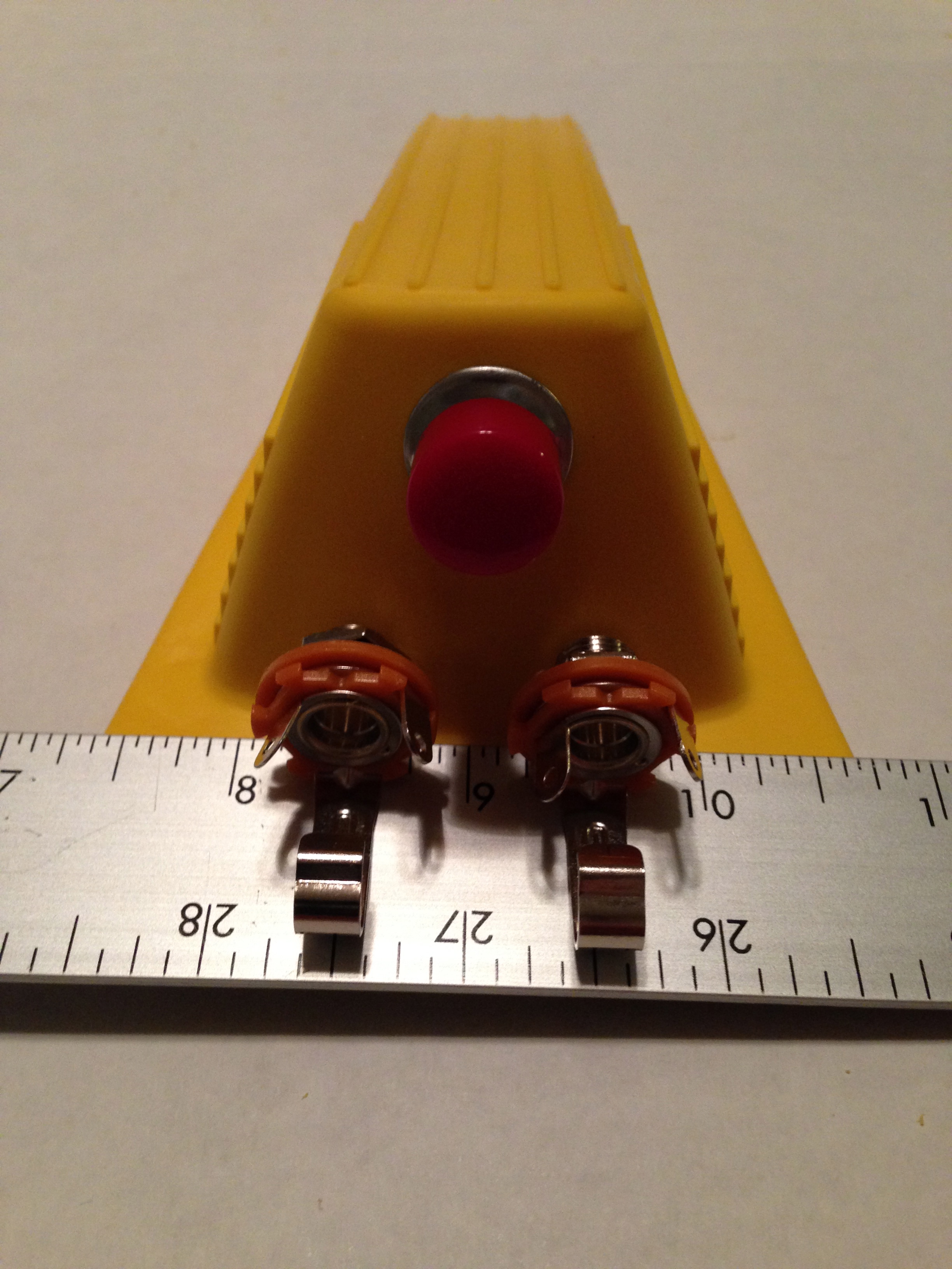
c. Set the two 1/4” jacks on the ruler, against the back of the doorstop about an inch apart and then mark a dot just above the center of each jack. Remove both the ruler and the jacks and inspect the markings. If they appear to be off in any way, wipe off the markings and repeat steps 2b and 2c. If they appear to be correct, proceed to step 2d.
d. Using a 1/2” spade bit/drill bit, place tip of the bit on the mark on the doorstop. Drill the hole. Do the same for the second mark. Clean up each of the holes by cutting away material with a hobby knife.
e. Unscrew the nut and remove the washer. Install the jack by pushing it through from the inside of the casing; replace the washer and then tighten the nut with pliers. Do the same with the second jack.
3) Install the momentary switch.
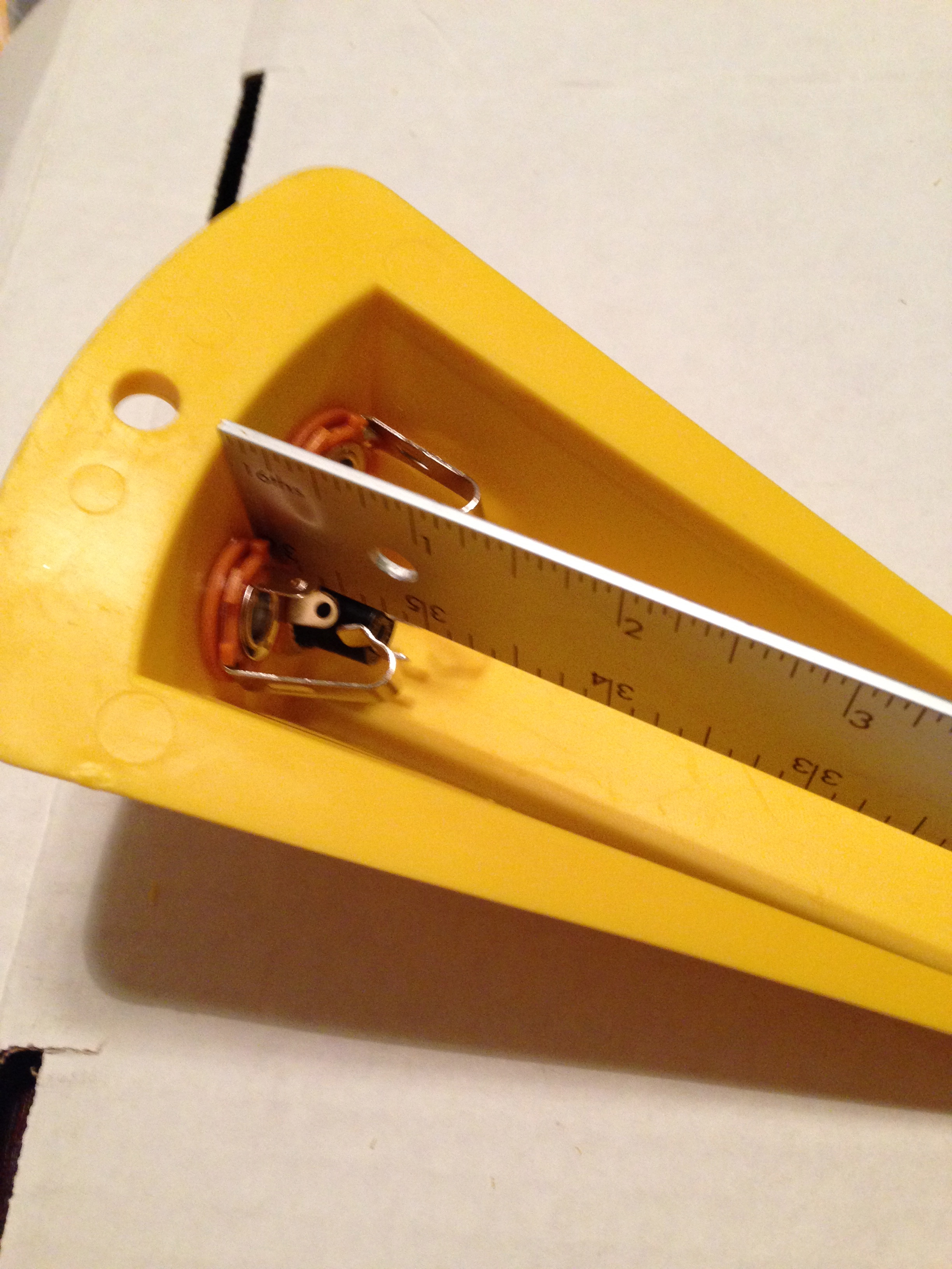

a. Flip the casing over and place the ruler against the back wall of the casing just above the installed on/off switch. Measure out from the wall, noting how far out the momentary switch will have to be located to clear the end of the on/off switch. In this case, it is one and a quarter inches.
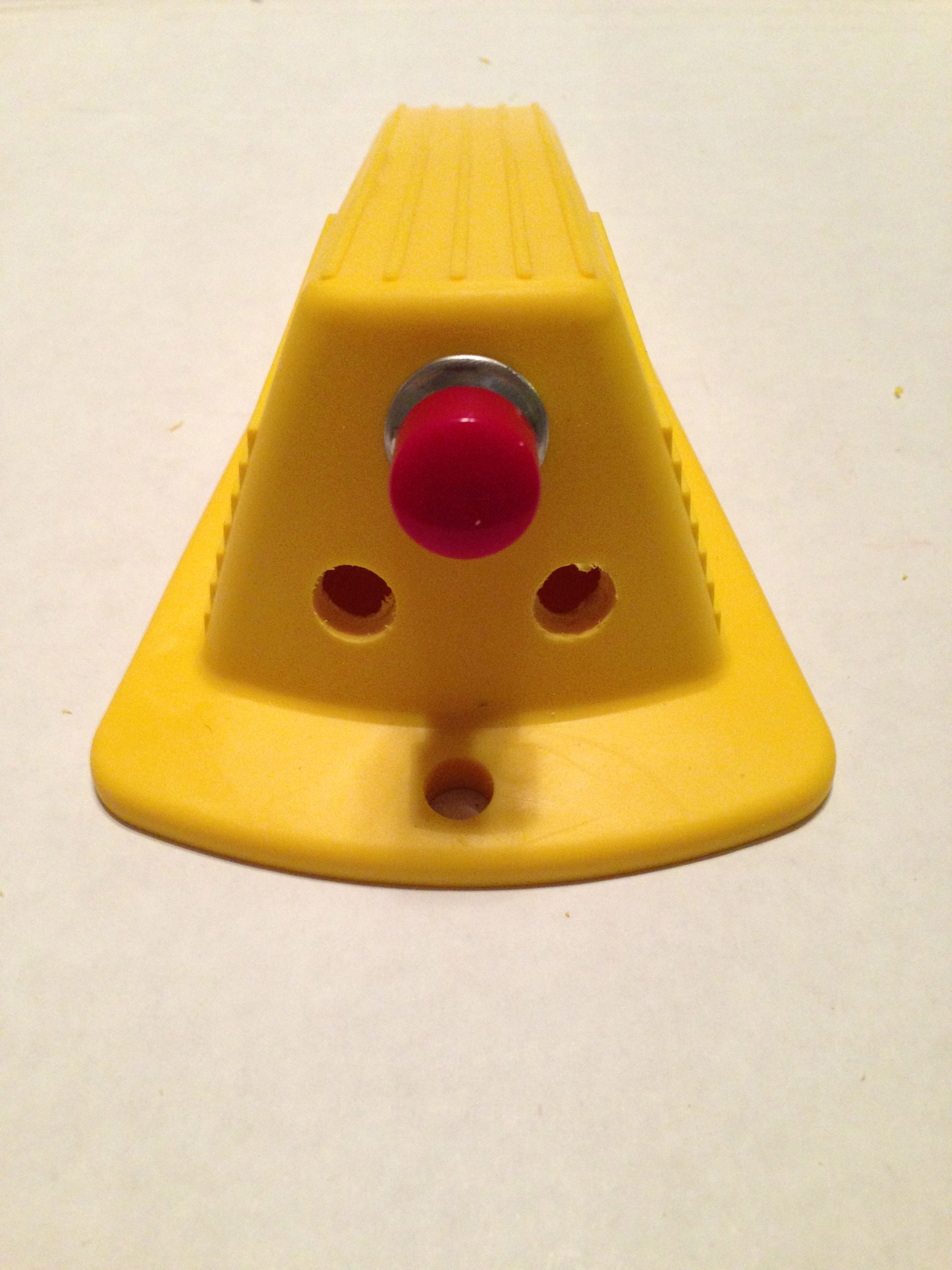
b. Set the casing right-side up. Place the edge of the ruler down the center of the casing, measuring from the top. Locate the correct measurement, which is, in this case, 1-1/4 inches, and mark it. If your casing has ridges like the example, use a hobby knife to cut away a small portion of the ridge about the size of the dot, so that the bit does not drill off center.
c. Place tip of the bit on the mark on the doorstop. Drill the hole and then clean the hole by cutting away excess material with a hobby knife.
d. Unscrew the nut and remove the washer. Install the switch and then replace the washer and tighten the nut with pliers.
4) Wire the unit. Using the chart below, apply the wires to the corresponding component terminals.


a. Note the distance between the on/off switch, momentary switch, and the two 1/4” jacks. Cut four red wires and one black wire to the appropriate length.
b. Strip about a 1/4” of insulation away from the wires on each end. Use a small pair of pliers to loop the exposed ends on each of the wires.
c. Attach the wires from the bottom up, starting with the lowest component in the casing. In this case, start with the on/off switch and attach a red wire to each of the terminals—one leading to the hot terminal on the 1/4” IN jack and the other to the hot terminal on the 1/4” OUT jack. To attach, slip the loop of the wire through the hole in the terminal and crimp it lightly with a pair of needle nose pliers.
d. Attach the black wire to the ground terminal on the 1/4” IN jack and lead it to the ground on the 1/4” OUT jack.
e. Attach a red wire to each of the terminals on the momentary switch—one leading to the hot terminal on the 1/4” IN jack and the other to the hot terminal on the 1/4” OUT jack.
f. Make sure that all of the connections are crimped and making solid contact.
5) Test the unit. Test the unit before soldering; it’s much easier to fix wiring mistakes.
a. Plug a guitar into the 1/4” IN jack and connect an amplifier to the 1/4” OUT jack.
b. Turn up the guitar, then power up your amplifier and turn up its volume.
c. Strum the guitar. If there is sound the pedal is in bypass; there is no sound the momentary switch is engaged and the pedal is on. Strum the strings, allowing them to ring, and then hit the on/off switch a few times—it should turn the sound on and off consistently. Leave the on/off switch with the sound off; strum the strings and press the momentary switch—the sound should turn on and off as you press and release. You may hear some crackling noise; this is likely because the loose wires are moving around and shorting out as they lose connection—it’s normal, but should go away after soldering the terminals. You will hear a faint click through the amplifier when you press and release the momentary switch; this is, unfortunately, a function of the switch and will happen most of the time.
6) Solder the unit.
a. Similar to wiring the unit, start with the lowest terminals and work your way up. Using a low wattage (15W-30W) soldering iron, place the flat edge of the tip against the terminal and press the solder against the area where the wire and terminal meet. Once the solder melts to a small bead, remove the solder and then the soldering iron. Do not leave the iron on the terminal for too long, as the component could melt—this is especially true with higher wattage soldering irons.
b. Repeat step 6a. for each of the terminals. If a terminal holds two wires, push them together as close as possible before soldering. After all of the wires are soldered, test each of the connections by pushing on the wires with a screwdriver and pair of pliers. If any of the wires move, the offending terminal must be soldered again, if nothing moves, the work is done.
c. Go back to step 5 and test unit as before. If everything works properly and there is only a faint click through the amplifier when pressing and releasing the momentary switch, the project is complete; if not, review the diagram against your unit’s wiring and read through step four again. If all of the wiring appears to be correct, there is always a possibility that there is a short in one of the wires that occurred while soldering the terminals. This can be easily checked by wiggling each of the wires while the guitar is playing—a shorted wire will cut in and out as the wire is moved. Earlier, we established that this unit can be used to break up the signal rhythmically, as in the Bulls on Parade scratch solo; however, it can also be used to effortlessly punch signal in and out.
Application:
Earlier, we established that this unit can be used to break up the signal rhythmically, as in the Bulls on Parade scratch solo; however, it can also be used to effortlessly punch signal in and out. For instance, let’s you have a riff that loops throughout the chorus that could use accent; the Rage Box can be used to momentarily add heavier distortion or a certain effect on the opening beat of the riff. In practice, you would simply run your signal through an AB box, the A side running straight to the amplifier with your primary signal and the B side detouring through the Rage box with the accent signal. This application makes the Rage Box a very practical unit that can be used in many creative situations.
Appendix:
| Parts List | |||
| Part Number | Quantity | Description | Vendor |
| 3763 | 1 | Shepherd Jumbo Door Wedge (doorstop) | Home Depot |
| 274-252 | 2 | 1/4” Mono Panel-Mount Audio Jack | Radio Shack |
| 275-609 | 1 | Momentary Switch | Radio Shack |
| 275-011 | 1 | SPST Push On-Push Off Switch | Radio Shack |
| Tool List | ||
| Part Number | Description | Vendor |
| —— | Drill | —— |
| —— | Spade Bit Set | —— |
| —— | Drill Bit Set | —— |
| 64-2055 | Soldering Iron (low wattage – up to 25 watts) | Radio Shack |
| 640-0017 | Solder (60/40 rosin-core) | Radio Shack |
| 278-1222 | 20 Gauge Solid Wire (three color pack – red/green/black) | Radio Shack |
| —— | Needle Nose Pliers (small) | —— |
| —— | Plier/Cutter Combo (small) | —— |
| —— | Screwdriver Set (mostly small) | —— |
| —— | Multifunction Wire Cutters | —— |
| —— | Channel Lock Type Pliers (small) | —— |
| —— | Ruler (flat preferred) | —— |
| —— | Felt-tip pen with fine point | —— |
For your amusement:
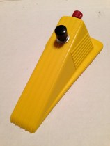
Here are some bonus pictures of my original revision of Dan’s Rage Box, constructed a year or so after Dan created his. Enjoy.


![]()
