


I turned off a bathroom light one evening and an automatic night light turned on. I flipped the switch on and off a few more times and watched the effect on the night light. The relationship between the bathroom light and night light, and the speed at which the nightlight was able to react reminded me of a tremolo effect. It seemed as if a strobe light with a speed switch would be adequate to control the sensor on the nightlight, and further that the sensor could be removed and applied to an audio signal, thus creating a variable tremolo effect.
This is an intermediate project involving the extraction of a photocell from a nightlight, and the addition of a switch and two audio jacks to an inexpensive strobe light. Depending upon the tools and supplies you already have, the materials necessary for this project will cost under $20 plus $8 – $20 (depending upon your desired option) to adapt the RCA jacks to 1/4 jacks. As a side note, any strobe light can be used to complete this project, the one that I selected is cost effective and flashes at a consistent speed; larger strobes would actually have more space inside, thus allowing the use of 1/4 jacks and eliminating the need for specialized cords or an adapter box.
Please read through the instructions before beginning; if you are prepared, and have everything on the list set up, you should be able to complete this project within a few hours–see the part/suggested tool list at bottom of the page. Click on any image to zoom in for a closer look.
Another stellar video for you. Turn off the lights and have a listen.
INSTRUCTIONS:
1) Open the strobe light casing.
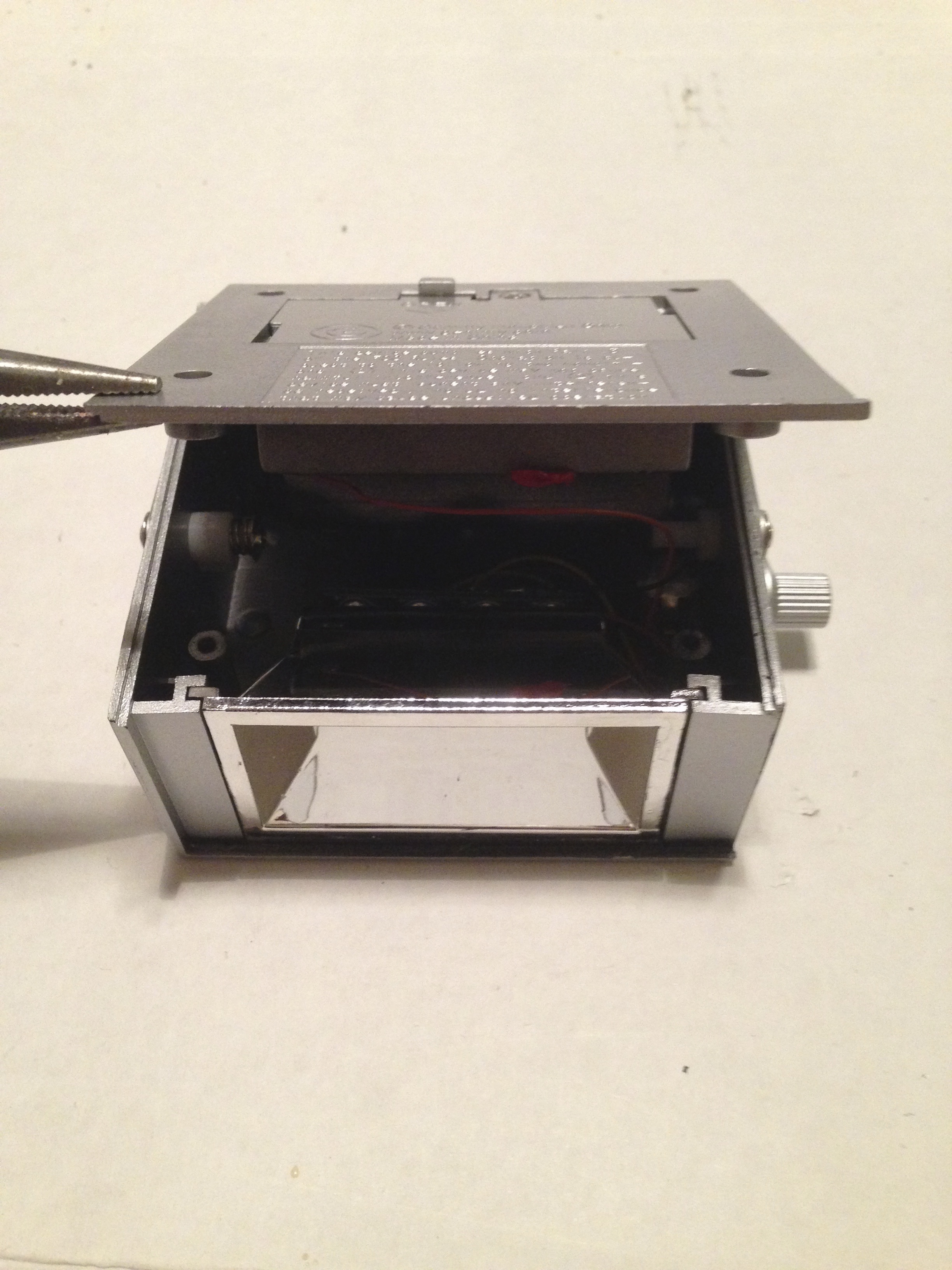
a. Remove the four screws. Slide the lens out from the side and set it aside. Using your fingers, pull up gently on the bottom and lift the cover off slowly—it is attached by wires. Set the lid to the side of the unit; the wires are long enough to keep it comfortably out of the way.
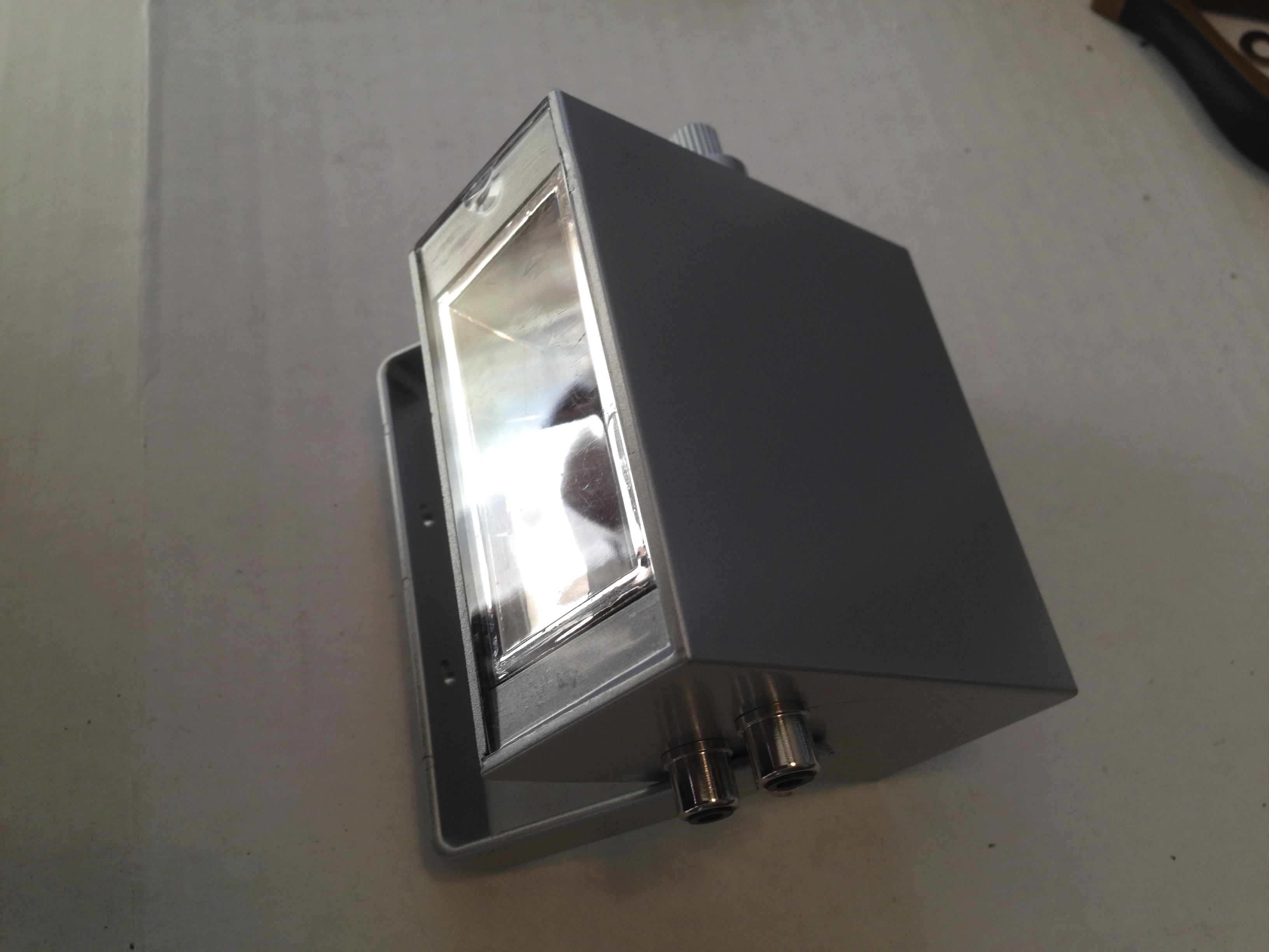
b. Look at the inside of the unit; there is very little open space to work with. In fact, there is just enough space for a small toggle switch and two phono jacks, which is why we are not using 1/4” audio jacks. With the back of the unit facing you the switch will be located to the left, diagonal from the variable speed knob. The phono jacks will be installed in a stack to the right, between the handle screw and the screw post.
2) Install the switch.
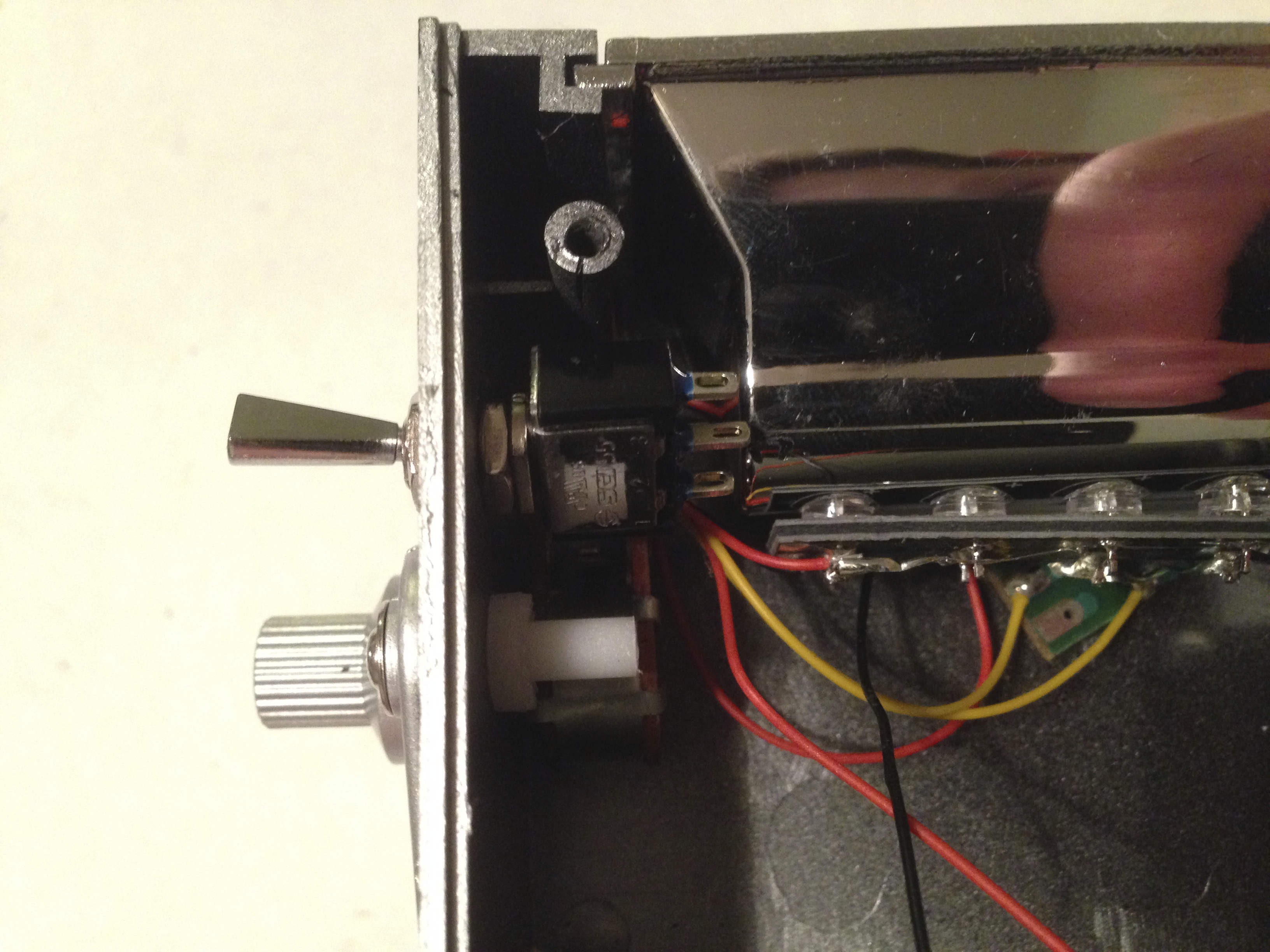
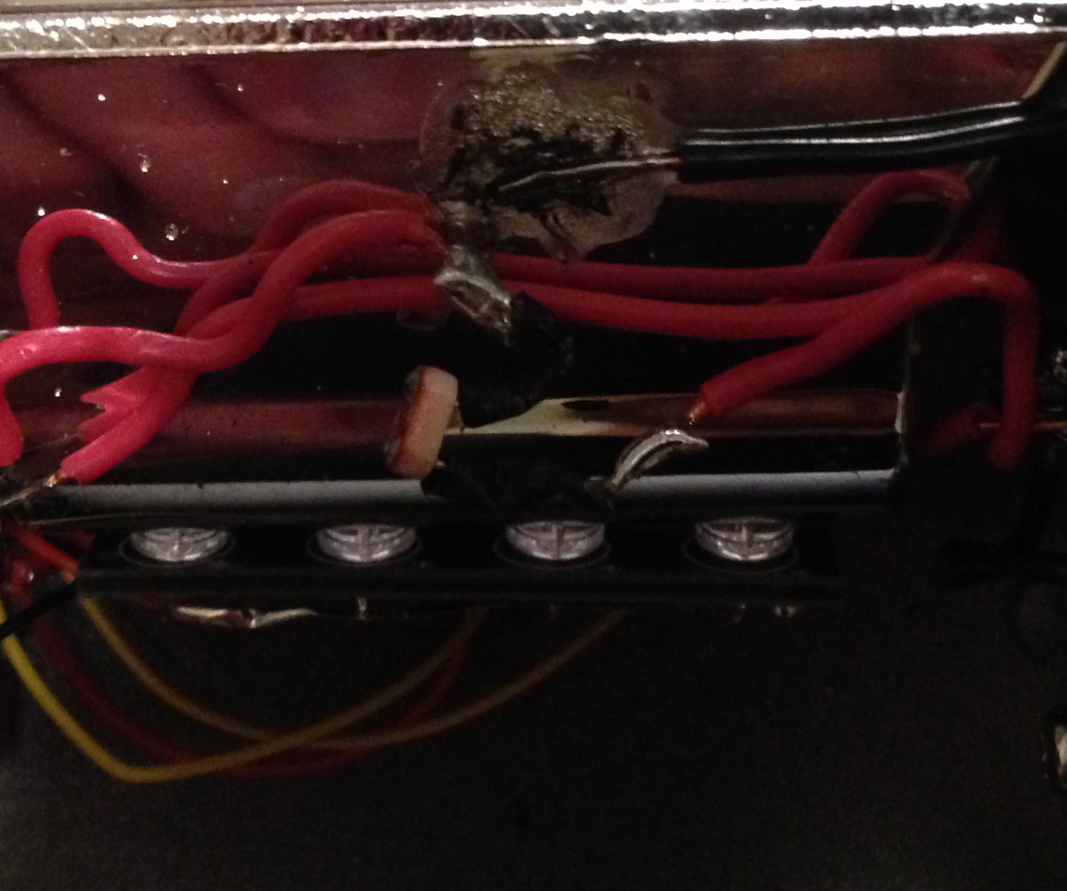
a. Inspect the inside and outside of the casing. Hold the switch up the inside wall of the unit and note where the switch terminals are just slightly above the interior light housing—it should be very close, but not touching. The length of the switch will be orientated parallel to the interior light housing (as seen in the picture); it will run diagonally on the outside of the casing. Estimate carefully; there is not much room for error, so try to be as precise as possible, allowing for both the light housing and the bottom cover plate.
b. Pick up a felt-tip pen and mark the outside of the casing, relative to the inside estimate.
c. Find a spade/drill bit that is slightly larger than the switch’s body. The switch shown will require a 1/4” spade bit or drill bit (you should drill a small pilot hole if using a drill bit—the spade bit is preferable).
d. Place the tip of the bit on the mark on the casing. Drill the hole, taking care not to hit any of the wires or interior components, and then clean the hole by cutting away excess material with a hobby knife and dump the debris.
e. Unscrew the nut and remove the washer from the switch. Install the switch and then replace the washer and tighten the nut with pliers.
f. Replace the bottom of the casing completely, to make sure that the switch is installed correctly. If the bottom does not close completely, turn the switch a bit; it may not be clearing the battery compartment. If it closes, the switch installation is complete—gently remove the bottom cover and set it to the side of the unit.
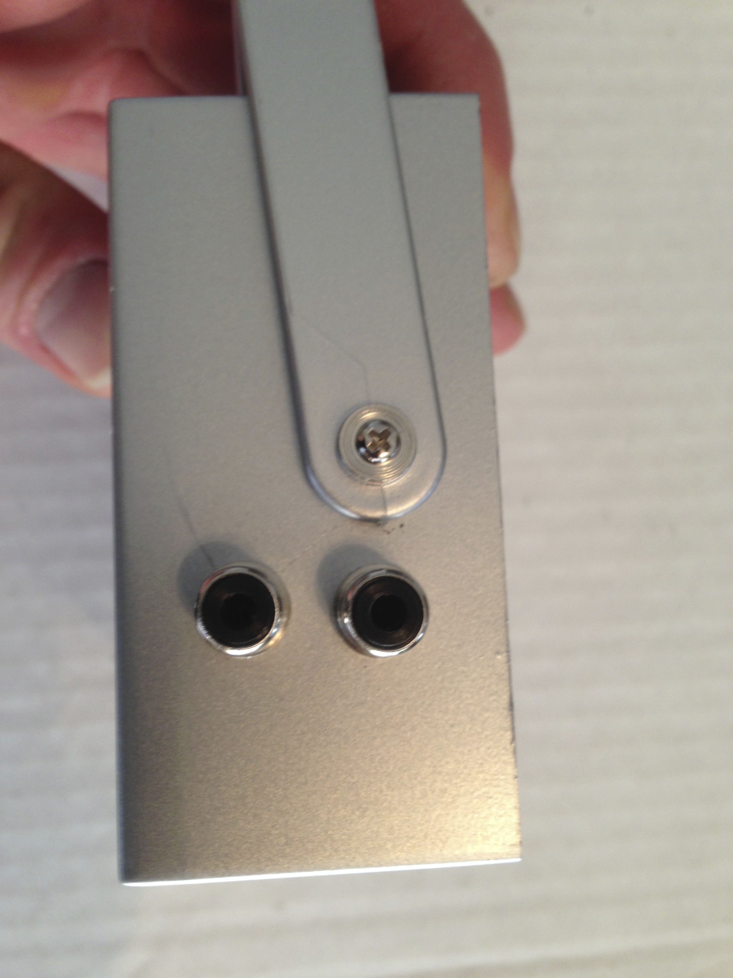
3) Install the two phono jacks.
a. Inspect the inside and outside of the casing. Hold a phono/RCA jack up the inside wall of the unit between the handle screw and the screw post, noting the center-most location for the jack. There is plenty of room to stack the two jacks.
b. Pick up a felt-tip pen and mark the outside of the casing relative to the inside estimate. Make the two markings about 3/4” apart and center them between the top and bottom of the casing, leaving at least 1/3” clearance above and below.
c. Find a spade/drill bit that is slightly larger than the phono/RCA jack’s body. The phono/RCA jack shown will require a 1/4” spade bit or drill bit (you should drill a small pilot hole if using a drill bit—the spade bit is preferable).
d. Place the tip of the bit on the mark on the casing. Drill the holes, taking care not to hit any of the wires or interior components, and then clean the holes by cutting away excess material with a hobby knife and dump the debris.
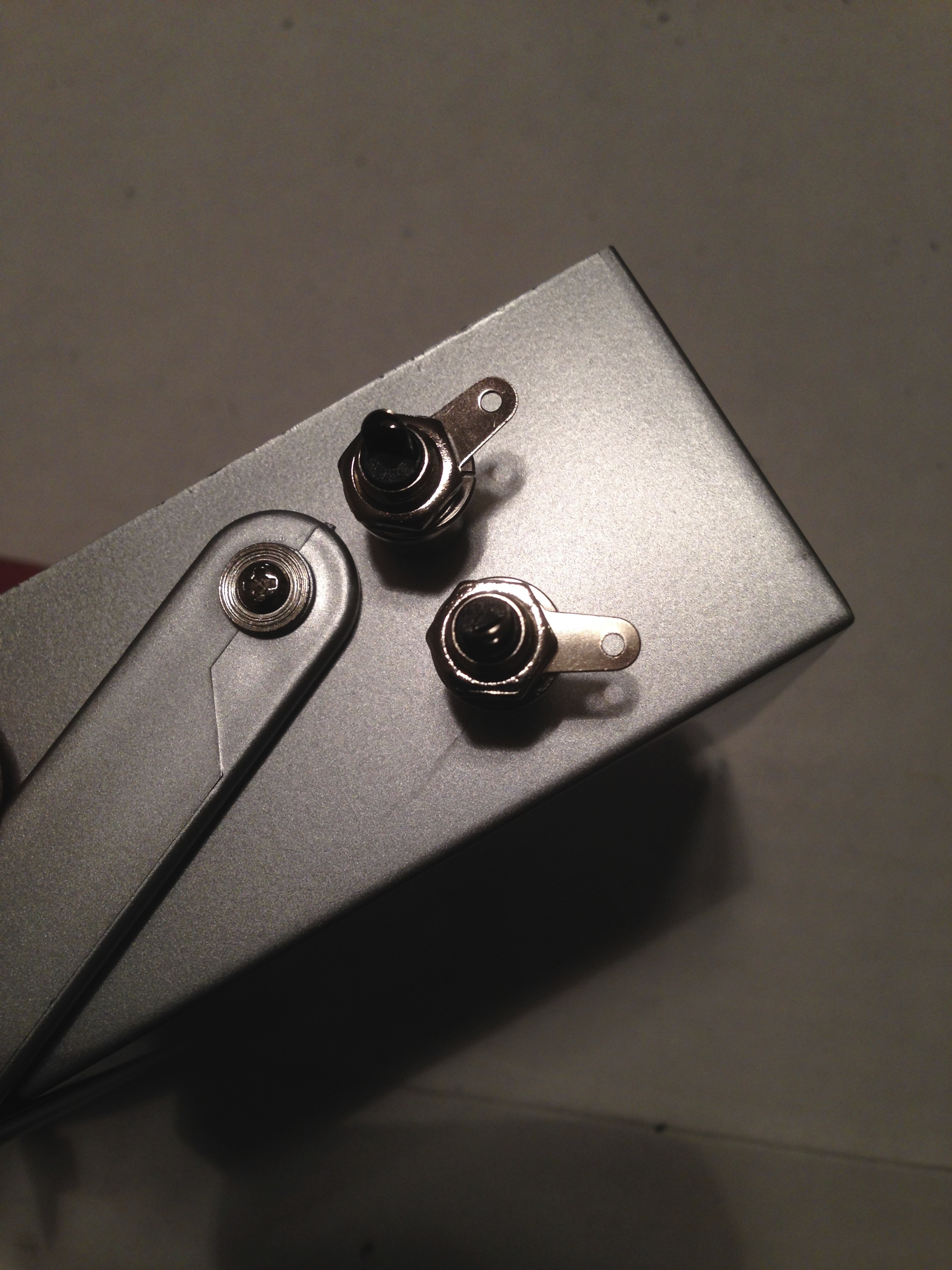
e. Unscrew the nuts and remove the grounding washers. Install the phono/RCA jacks and then bend flat grounding washers away from the casing. Replace and tighten the nuts with pliers.
4) Extract the photocell from the nightlight.


a. Slide the lens/guard off of the casing and set it aside.
b. Unscrew the lightbulb and set it aside.
c. Twist and pull off the collar.
d. Remove the screw and gently pull the casing apart.
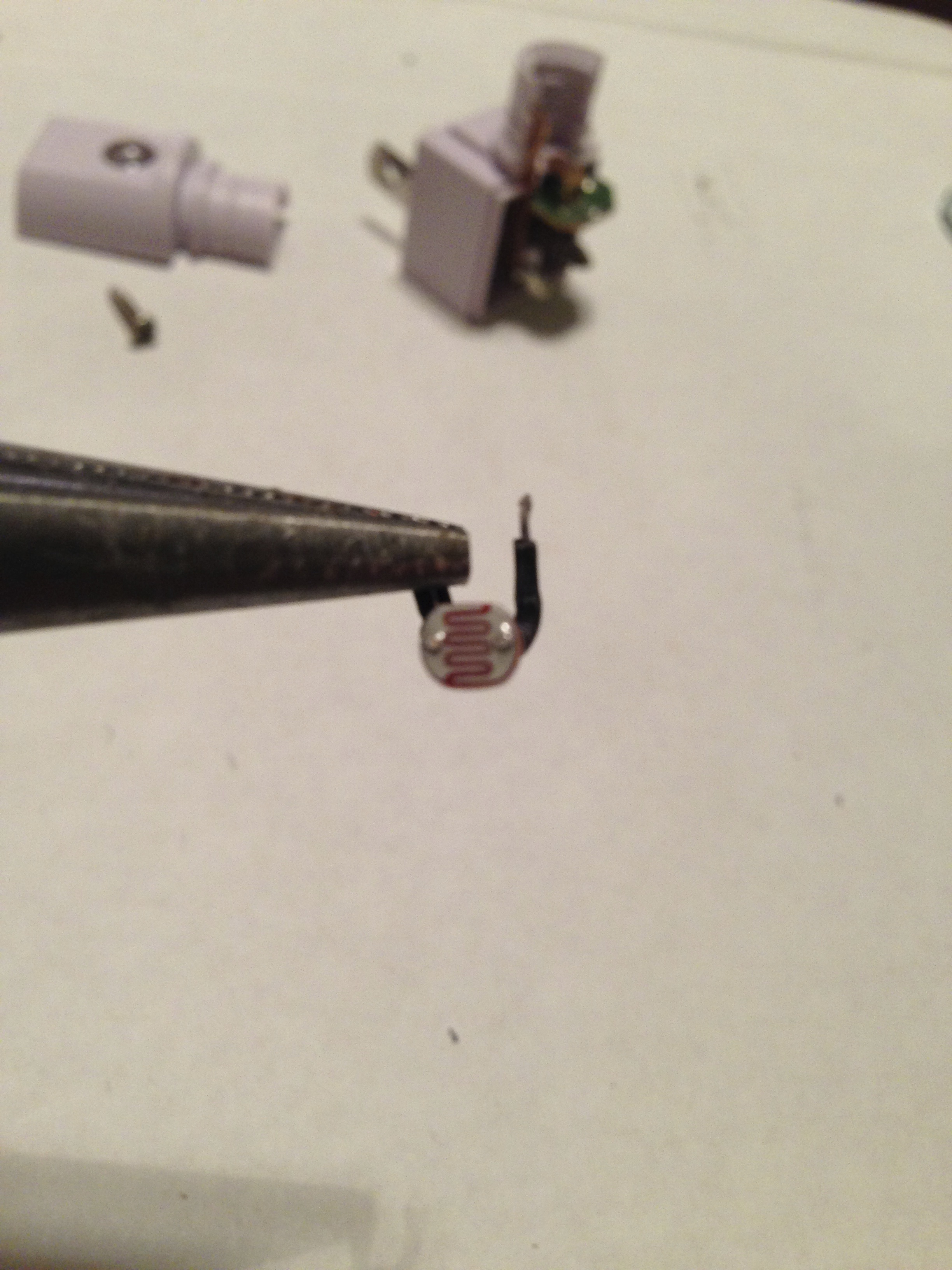
e. Locate the photocell—it should be round with a squiggly line and two wires coming out of it. Both photocell wires will be soldered to the board. You must heat the solder with a soldering iron and gently remove each of the wires from the board one at a time. Place the casing in a vice; if you do not have access to a vise, ask someone to help you. Grip one of the wires (not the photocell) with a pair of needle nose pliers and pull the wire away from the board as you melt the solder. Repeat for the second wire.
F. Once the photocell is free from the board, set it aside for a moment.
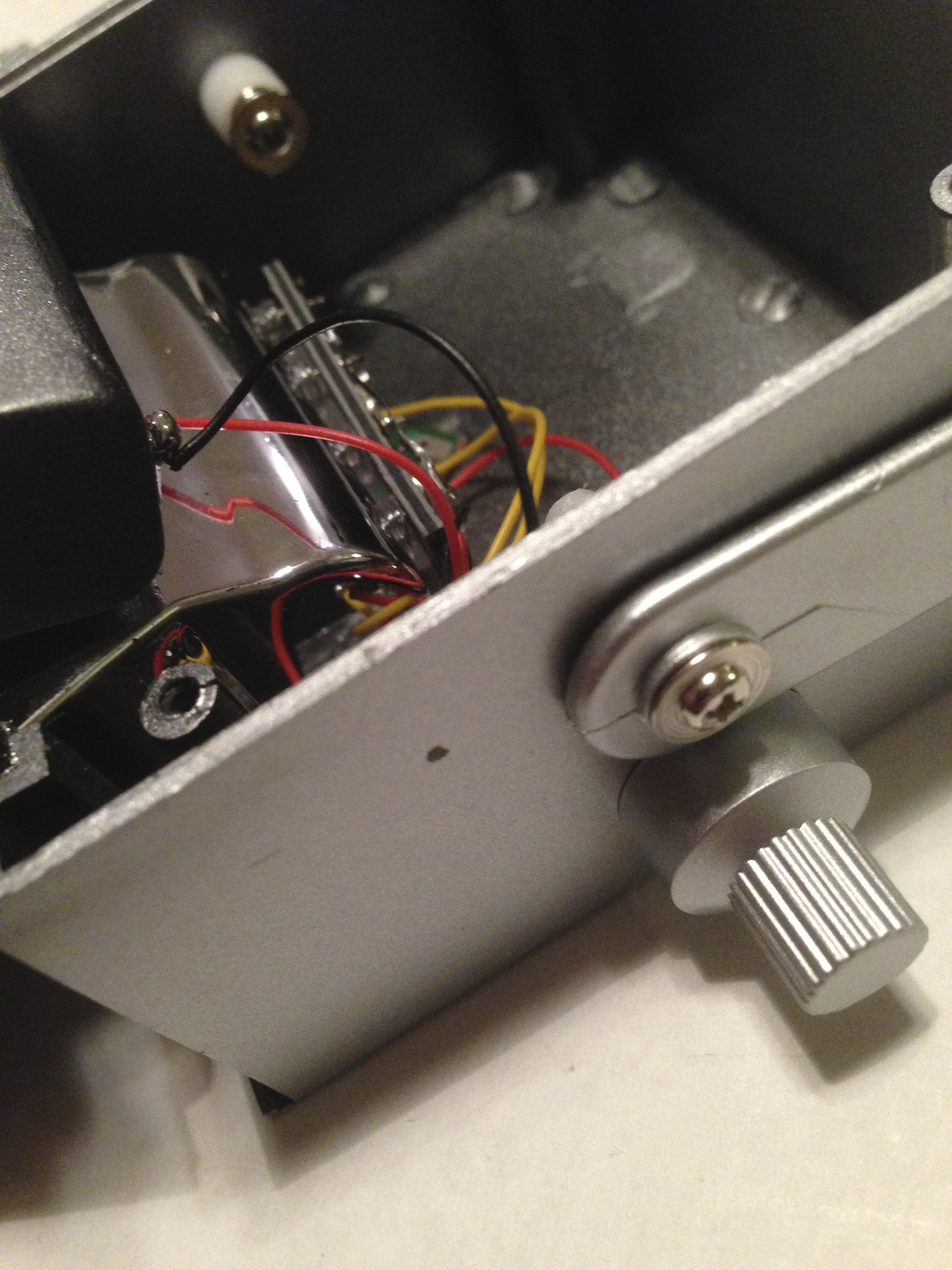
5) Wire the unit. Using the chart below, apply the wires to the corresponding component terminals
.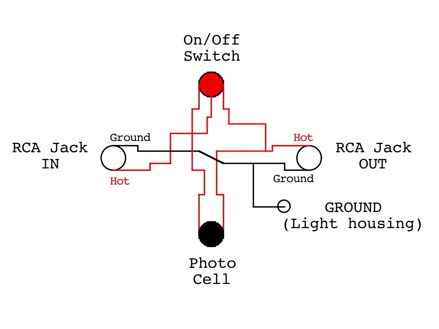
a. Note the distance between the SPDT switch, and the two phono/RCA jacks—cut two red wires.
b. Strip about a 1/4” of insolation away from the wires on each end. Use a small pair of pliers to loop the exposed ends on each of the wires.
c. Attach the wires from the bottom up, starting with the lowest component in the casing. To attach, slip the loop of the wire through the hole in the terminal and then crimp it lightly with a pair of needle nose pliers. Attach one end of a red wire to the center (hot) terminal of the lowest phono/RCA jack (audio IN) and the other end to the center terminal of the switch. Attach one end of the second wire to the center (hot) terminal of the upper phono/RCA jack (audio OUT) and the other end to the lower side terminal on the switch.
d. Note the distance between the two phono/RCA jacks. Cut a length of black wire that is one and a half times that distance. You will want enough length to allow slack to loop outward so that there is ample room to solder. Attach one end of the black wire to the hole in the grounding washer on the lower phono/RCA jack and the other to the grounding washer on the upper phono/RCA jack.
e. Cut a length of black wire that will run between the grounding washer on the upper phono/RCA jack and half the distance of the light housing. Attach one end of the black wire to the grounding washer on the upper phono/RCA jack and solder the other end to the top/center of the light housing.
f. Hold the photocell up to the center of the light housing. Note the distance between the left wire on the photocell and the upper terminal on the switch and then the right wire on the photocell and the center (hot) terminal on the upper phono/RCA jack. Cut two lengths of red wire one and a half times that distance. You will require extra space when setting the proper direction for the photocell. Apply solder to (tin) the end of both wires on the photocell. Apply solder to (tin) one end of each of the red wires. Apply a large bead of solder to the end of each wire on the photocell. Heat one of the solder beads and then hold one of the red wires against one of the photocell wires and spread the solder over both of the wire ends, binding them together—do the same for the other red wire and the remaining photocell wire. Wrap a small amount of electrical tape around both of the joints.
g. Attach one of the red wires bound to the photocell to the upper terminal of the switch and then the other red photocell wire to the center (hot) terminal on the upper phono/RCA jack. Place the photocell and its red wires close to the light housing.
6) Test the unit/Move the photocell to the correct position to catch light on the inside of the box.
a. Hook up the unit using two specialized cords with a 1/4” plug on one end and a phono/RGA plug on the other—unless you have another means available. Place one cord between your instrument and the phono/RCA IN jack and the other between the phono/RCA OUT jack and your amplifier.
b. Turn on the unit and your amplifier. The strobe light should be flashing.
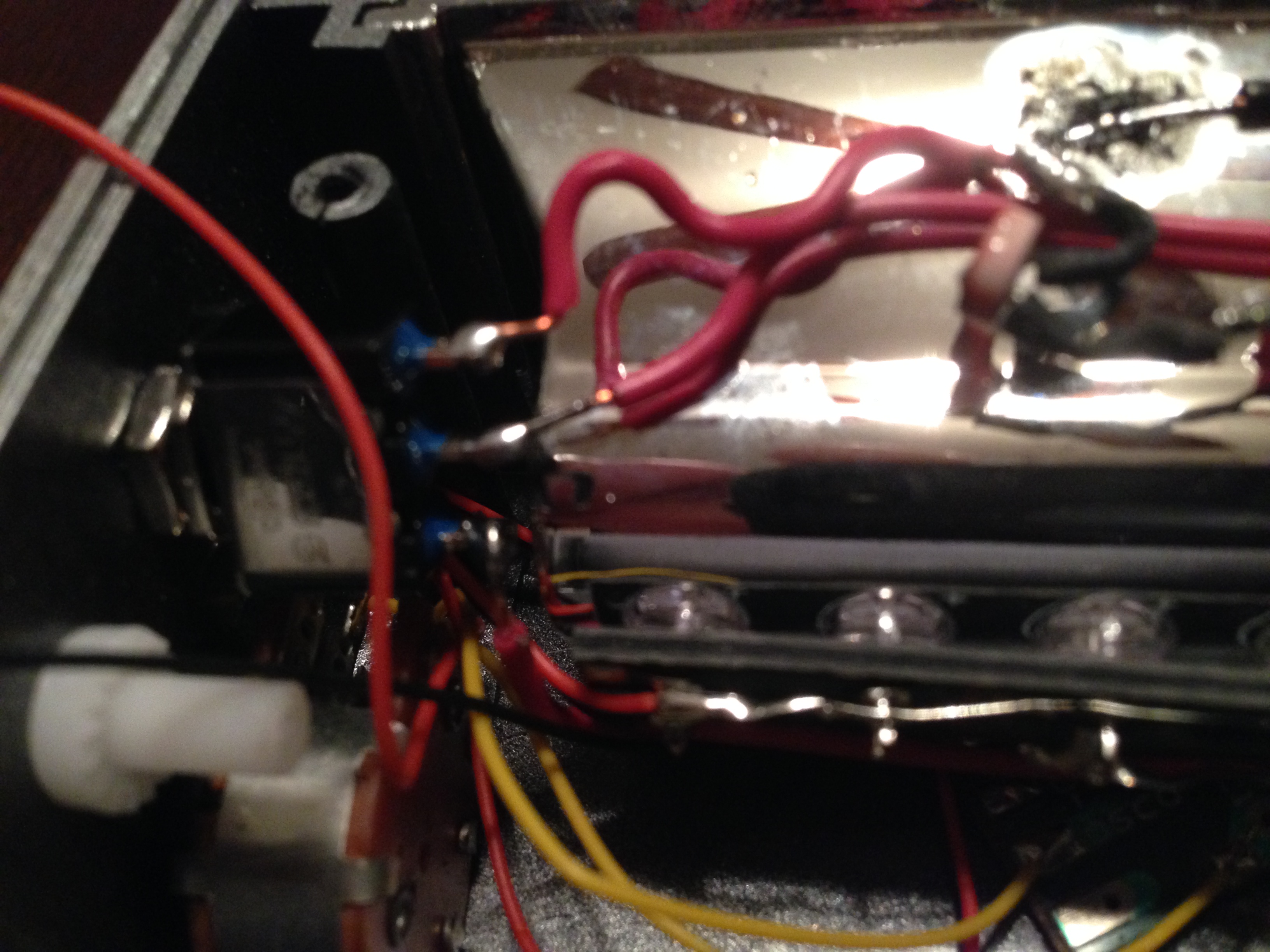
c. Turn off the lights in the room—make the room as dark as possible. Note where the strobe lights light falls on the inside of the box. Start with the photocell in the position shown in the image provided. The photocell should be adverted away from the direct light— direct light does not allow the photocell to recover as quickly, thus weakening the effect. Play a note on the instrument and let it ring. Slowly move the photocell in and out of the direct light until it seems to be in an optimum position. Play the instrument, turning the unit’s control knob up and down to check the unit at fast and slow speeds.
d. Test the switch. It should toggle between bypass and the tremolo effect.
e. When you are satisfied with the photocell placement, turn on the lights. Carefully replace the cover and install a couple of screws.
f. Turn off the lights and test the unit as before, to make sure that the photocell was not knocked out of place while replacing. If the unit is not working properly, remove the cover and test the wires to make sure that they are secure and the check the photocell placement; if it is, congratulations. You may notice that the unit has a less pronounced tremolo effect when the lights are on. This is caused by outside light entering the unit through holes in the reflector. If this happens, simply place the lens against something or the unit inside of something or place some removable painter’s tape over the lens to reduce the amount of light bleeding in.
7) Solder/Close the unit.


a. Solder each terminal, starting with the lowest terminals.
b. Check the wires to make sure that they are secure by pushing on them with a pair of pliers or a screwdriver.
c. Close the lid and install the screws.
d. Test one last time.
8) Fabricate an adapter box. Step 5 could be optional, but since the casings limited space necessitated the use of phono/RCA jacks, we must adapt them to the 1/4” jacks found on your guitar and amplifier. You have three options: use a small 1/4” jack to phono/RGA jack adapter (under $8 for two), a specialized cord that has a 1/4” plug on one end and a phono/RGA plug on the other (under $14 for two), or an adapter box that adapts two phono/RCA jacks to two 1/4” jacks with the use of a stereo RCA cable (under $10 for the box if you have you have two phono/RCA jacks left over from the four-pack and an extra $4 if you don’t already own a stereo RCA cable—under $15 at the most. The small adapters are the most cost effective, but the adapter box could be more versatile in the long run. I would suggest two of the specialized cords with a 1/4” plug on one end and a phono/RGA plug on the other—they will make testing your tremolo less complicated and are great for introducing hi fi stereo equipment into your instrument’s signal chain.
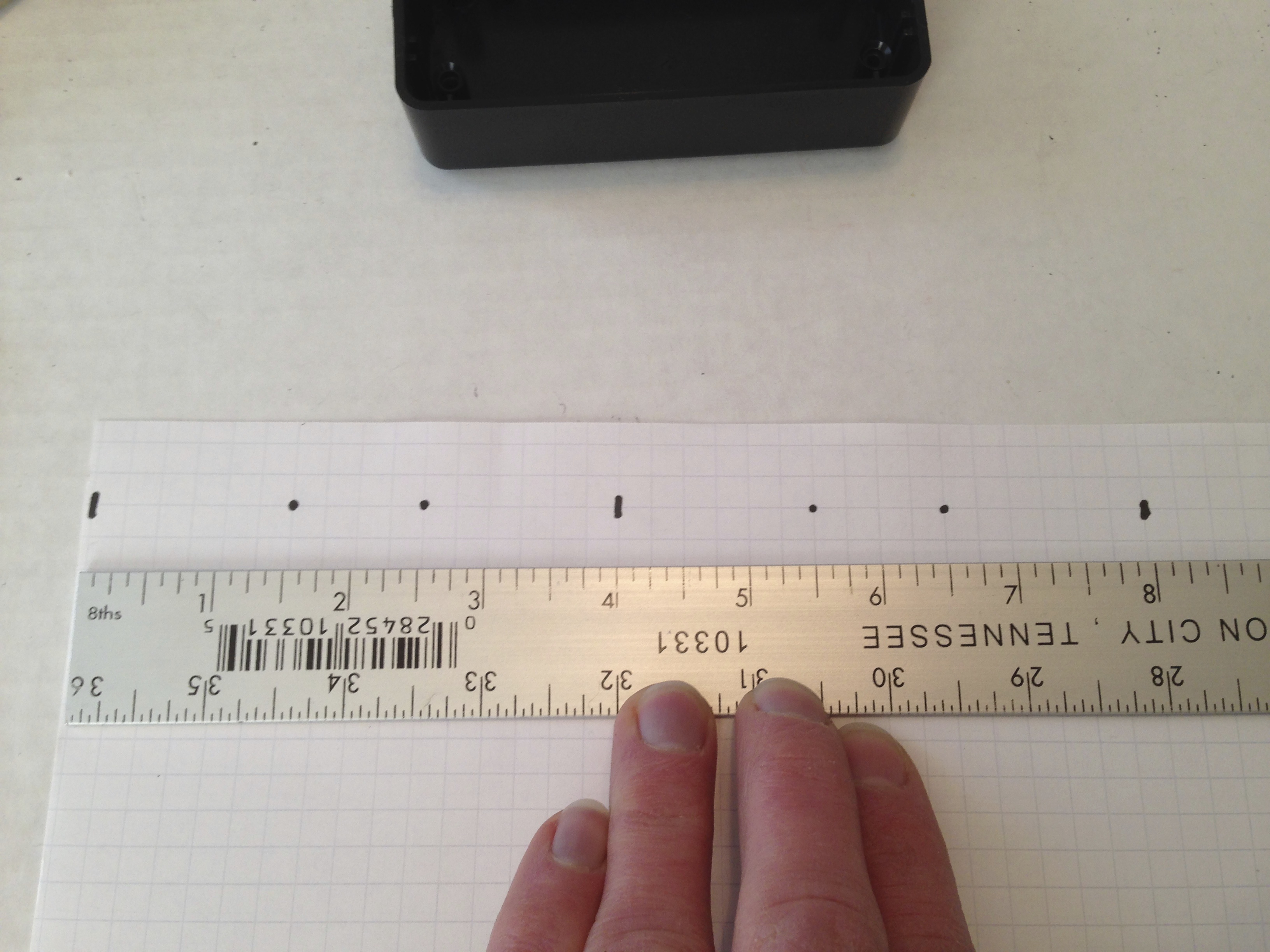


a. Pull the lid off of a 2x4x1 box and set it and the bag of four screws aside.
b. Make a template. Using four line per inch (16 squares per square inch) graph paper, cut out a 1×4 section (based upon the bold lines; try to be as precise as possible.
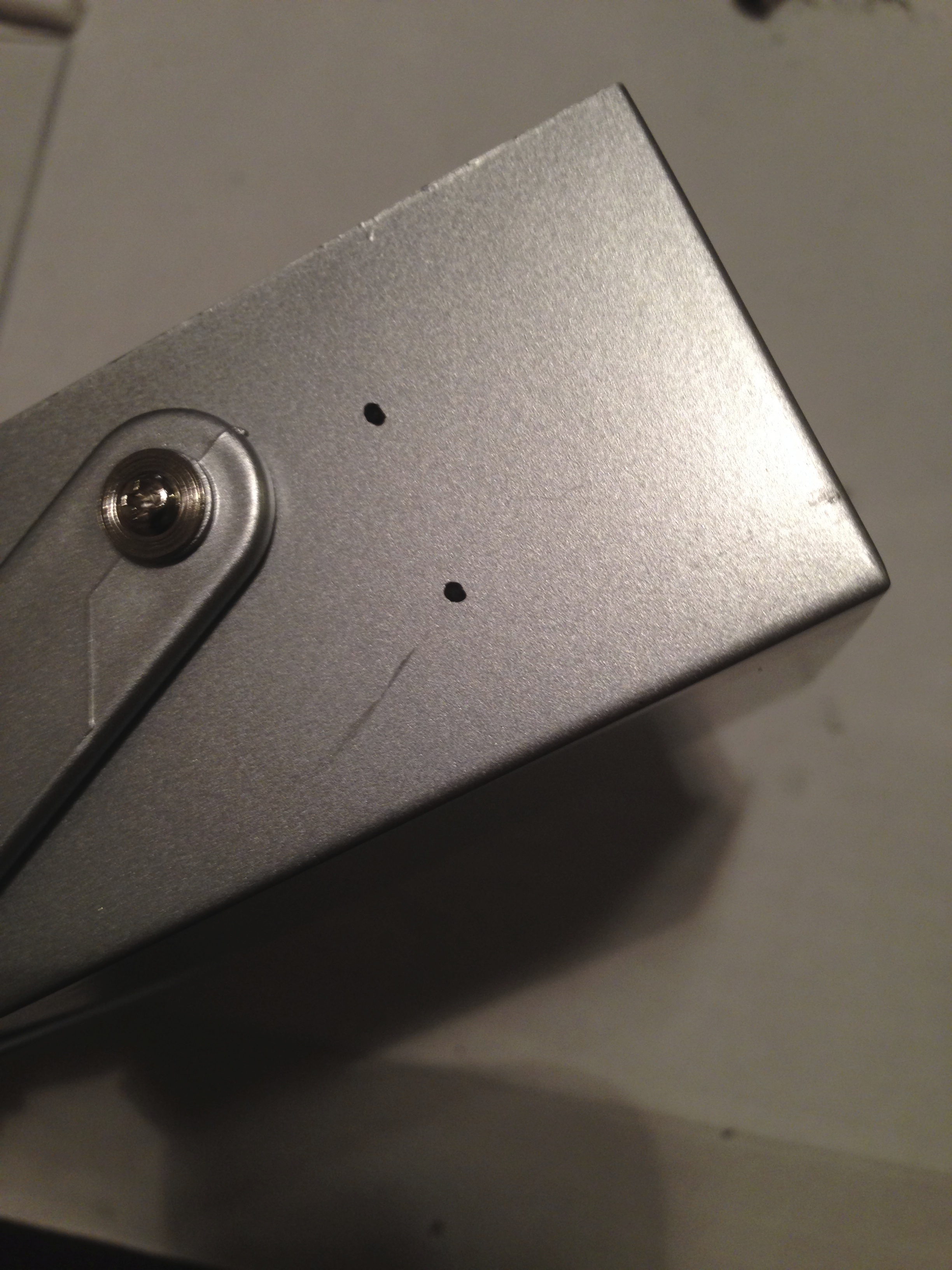
c. On the 1×4 template, starting in the upper-left corner count six squares over to the right and two squares down (1-1/2×1/2) and draw a small dot at the intersection, then in the upper-right corner count six squares over to the left and two squares down (1-1/2×1/2) and draw a small dot at the intersection.
d. Apply small pieces of painter’s/masking tape to either side of the 1×4 template, as if you are going to tape it to something. Line up the template, level and centered, on one of the 1×4 sides of the box and then tape it down.
e. Drill pilot holes. Using a small diameter drill bit, drill the two dots designated on the template. Remove the template, if it is in usable shape, apply it to the opposite 1×4 side of the box and drill two more pilot holes; if not, make another template, repeating steps b – e—usually, it is fine to use again.
f. Drill holes for two phono/RCA jacks and two 1/4″ jacks—I recommend a 1/4″ spade bit for the phono/RCA jacks and a 3/8″ spade bit for the 1/4″ jacks. When drilling downward, helps to put a small piece of wood inside the box to protect the opposite side from damage when the hole is complete and the bit suddenly drops to the bottom.
g. Install the two phono/RCA jacks. Unscrew the nut and remove the grounding washer. Install the phono/RCA jack by pushing it in from the outside; then bend flat grounding washer away from the casing. Replace and tighten the nuts with pliers. Do the same with the second jack.
h. Install the two 1/4″ jacks. Unscrew the nut and remove the washer. Install the jack by pushing it through from the inside of the casing; replace the washer and then tighten the nut with pliers. Do the same with the second jack.
i. Wire the unit. Note the distance between the phono/RCA jacks and the 1/4″ jacks. Cut two red wires and two black wires one and a half times that distance. Attach one end of a red wire to the hot terminal running to the tip on the left-hand 1/4″ jack and attach the other end to the hot center terminal on the phono/RCA jack directly across from it. Attach one end of a black wire to the ground terminal on the left-hand 1/4″ jack and attach the other end to the grounding washer terminal on the phono/RCA jack directly across from it. Do the same with the right-hand 1/4″ jack and phono/RCA jacks.
j. Solder each terminal. Check the wires, by pushing on them with a pair of pliers or a screwdriver, to make sure that they are secure.
k. Place the lid on the box and fasten the screws.
Check out this video:
Appendix:
| Parts List | ||||
| Part # | Qty | Description | Vendor | Price Ea |
| 1 | Gemmy Mini Strobe Light (optional) | Walmart | $4.99 | |
| 275-635 | 1 | SPDT Metal Toggle Switch | Radio Shack | $3.99 |
| 274-346 | 2 | RCA Phono Jack – 4-pk | Radio Shack | $4.49 |
| 523131 | 1 | Night Light – automatic w/ photo cell – 4-pk | Lowes | $4.98 |
| 270-1802 | 1 | Project Box 4x2x1 (adpt box option) | Radio Shack | $3.99 |
| 274-346 | 2 | RCA Phono Jack (adpt box option) | Radio Shack | $4.49 |
| 274-252 | 2 | 1/4” Open Jack – 2-pk (adpt box option) | Radio Shack | $5.49 |
| 42-897 | 1 | Stereo RCA jack cable (adpt box option) | Radio Shack | $3.99 |
| 42-2373 | 2 | 1/4” to RCA cable (special cord option) | Radio Shack | $6.49 |
| Tool List | ||
| Part Number | Description | Vendor |
| —— | Drill | —— |
| —— | Spade Bit Set (preferred) | —— |
| —— | Drill Bit Set | —— |
| 64-2055 | Soldering Iron (low wattage – up to 25 watts) | Radio Shack |
| 640-0017 | Solder (60/40 rosin-core) | Radio Shack |
| 278-1222 | 20 Gauge Solid Wire (three color pack – red/green/black) | Radio Shack |
| —— | Needle Nose Pliers (small) | —— |
| —— | Plier/Cutter Combo (small) | —— |
| —— | Screwdriver Set (mostly small) | —— |
| —— | Multifunction Wire Cutters | —— |
| —— | Channel Lock Type Pliers (small) | —— |
| —— | Ruler (flat preferred) | —— |
| —— | Felt-tip pen with fine point | —— |
![]()
